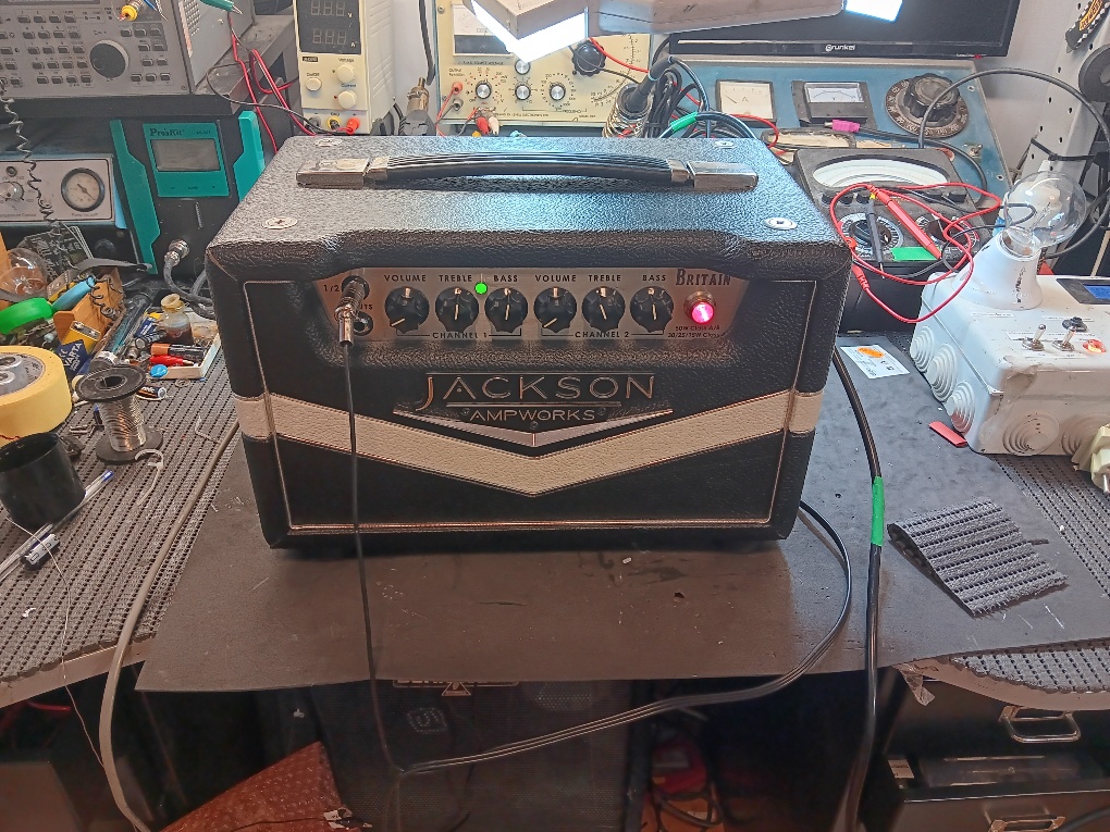
Jackson “Britain 4” Amplifier.
Well, I have not seen one of these before in my years for servicing amplifiers. So, was all excited to have a look and to see what it was made of. The client said there was no output. Perhaps a fuse I thought, but no….
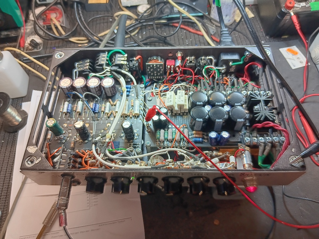
For those of you that are not familiar with this little boy, it hides some secrets. Taking the back off, I saw 2 nice big transformers. That’s good. And, 2 x EL34s. Okay, all standard. Having a quick test, the amplifier was taking about 100 Watts in standby and about 130 with the HT on. Quite high I thought. This indicated the output section was working, especially as the 2 X EL34s were getting hot. Once the chassis was out of the cabinet, I was amazed to see 4 x EL84s plus 4 valves in the pre amp section. A switch on the rear of the chassis said you could switch between various output configurations. There were also 2 fans to blow away the heat generated by this family of valves.
Certainly no output was true. I checked the HT on the valves and all seemed to be okay. In fact, injecting a signal on the grids of the output valves produced sound. With a signal connected to the input, I was amazed to see no output from the first anode of the pre amp valve. Although It had plenty of HT volts. What’s was happening?? I looked at the first valve and saw it was an EF86. Most strange. I searched for a schematic, but none of the normal sites had anything. Even Jackson, the manufacturer said they had nothing… But someone did confirm an EF86 was correct.
Then… I noticed all the 4 preamp valves were cold. A check on the heater pins showed nothing. The circuit boards are well marked thankfully. LT+ and LT- links were missing a supply. Marked like this, meant that the heater supply was DC. Looking at the circuit boards, I said a little prayer hoping that there was not a power supply fault. This would have meant a major time investment. Looking at the heater supply, showed a dead short circuit, looking at the pre amplifier section. The power supply had no shorts. With the pre amp board disconnected, and valves removed the short was still present. The only things left to test were the LT smoothing capacitors soldered to the underside of the PCB. Was the problem caused by one of these? So, connect a bench supply to the heater connection and see what current we have. I left it at 2 Amps for a few seconds. Ahahahah. One of the 4 x 4700UF started to get hot. A quick call to the capacitor police and we had him in custody and a replacement fitted.
With all the valves fitted and a meter connected to the heater supply, the power was switched on. I became very depressed to see only 2 volts DC. Had the short circuit damaged the power supply? If so, a nightmare of board removal would have presented itself, plus my heavy drinking again starting. But, as I watched, the heater voltage increased to 6.3 VDC. Wonderfully, there was a heater soft start circuit! This limits the current when the filaments in the pre amp valves are cold and prevents heater flash.
So, everything packed up and tested. I have to say, the build quality is good and the components are good. The PCB is marked with component values. I don’t like the fact the PCBs are coated both sides, so you cannot see the track layout. There is an awful lot of stuff squeezed into a tiny box. Servicing is not the easiest of tasks. But I had a respect for this little boy who could certainly punch way above its weight.