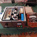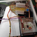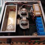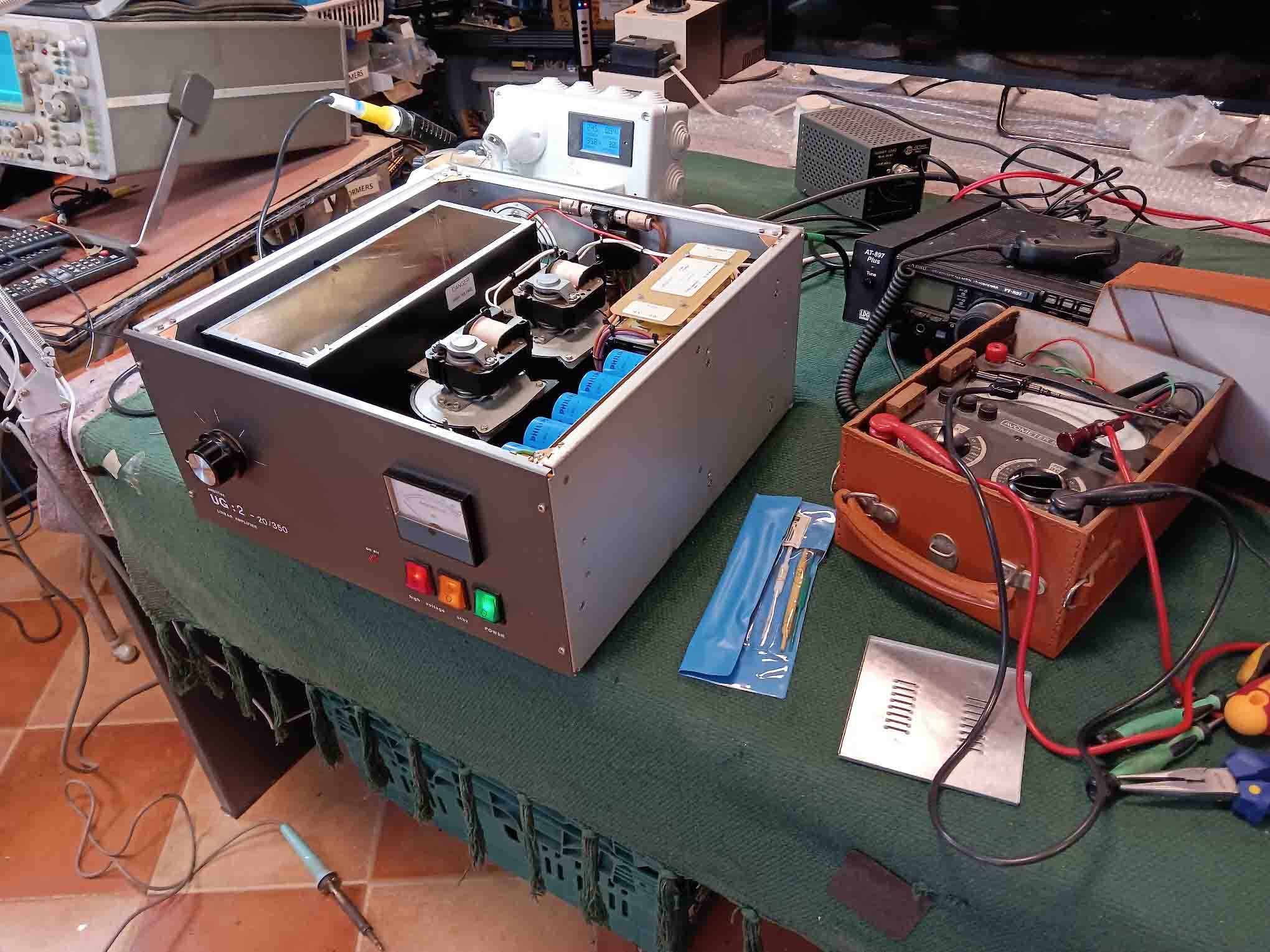
Amplitec VHF Linear amplifier UG 2-30/350
This is a well built nice linear amplifier. Basic design and enough space to be able to work on it internally.
The original fault was very low output. With an exciter input of some 20 Watts, little more than that was coming out. The owner had purchased 2 “new” valves, GI7b. These are quite rugged Russian built valves, or tubes if you are from the U.S. of A
With the original valve out and one of the new ones fitted, the amplifier was powered up. A few minutes to warm up then switch on the HT. Out goes all the lights. That was disappointing, wasn’t it? So, with all HT feeds separated a hunt for shorts started. Nothing nasty could be seen. With connections all back on except for the Anode feed (plate), we powered up with current limiting and Variac. All good. Same thing with the valve now fully connected. When the HT was raised to 1.5kV, horrid pops could be heard and HT current spiked. With the valve removed and subjected to an insulation test, it was clear it had gone to air. Looking at this “New” valve, it was clear that it had been subjected to a serious wallop at some point. So, in with the second “new” valve, which actually look nice and fresh. All confidence spilling everywhere, powered up, no nasty events and keyed up the exciter, looking forward to a healthy output. Oh no. Nothing.
Managed to get a circuit diagram. After much head scratching, voltage readings around the cathode were ridiculously high, varying around 150VDC. The cathode bias is achieved by it’s connection to ground through a variable 2 transistor constant current arrangement. The emitter of one transistor should be connected to ground, but is wasn’t. That explained why the cathode voltage was way high and the valve was not passing current. Off with the control board and several dry joints were found. After a reassemble and an adjustment of the bias, we ere getting 350 Watts out for 20 Watts in.
I always tell people, don’t blame the valves first. Should have listened to myself for a change.