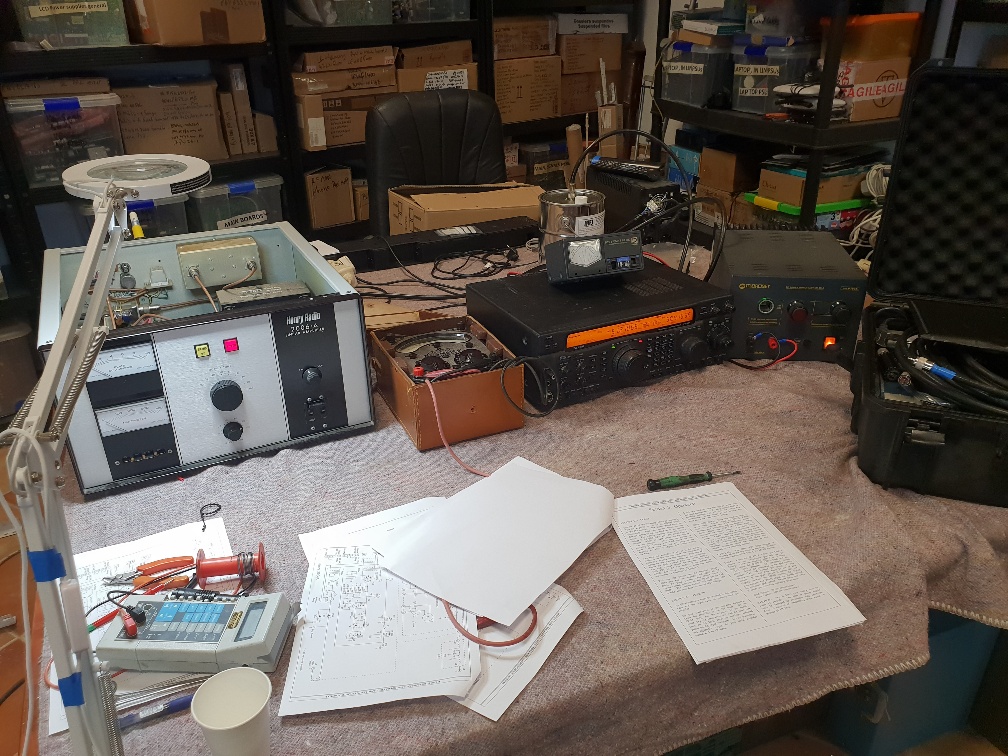
Henry Radio 2006A
When someone says to me “I bet you like a challenge?” my answer nowadays is NO. I like a job that I can complete quickly, doesn’t make my head hurt and I can earn enough to feed myself. This job did not meet any of my desires.
This RF linear power amplifier came in from a friend who is a well established radio ham here in Spain, Andy Durrant, EA7KBX. At time of writing he does a lot of communicating around the 50 MHz 6 mtrs, (data etc.) band and now he has lots of nice new antennae up in the air, this amplifier is needed. But, it became unwell. The report was that there was no output and the triode valve was getting hot enough to melt the pain off his neighbours’ car parked 100 mtrs down the road.
With the Henry Radio 2006A amplifier on the bench, hooked up to a Yeasu transceiver as a RF source, big dummy load. I keyed it up. The plate current (anode to us Brits) was high and the grid current was also off the scale. The transceiver, although set to a couple of watts output was reading 40 watts on its built in meter. Something evil was happening. Shut down before damage was done.
These Henry Radio amplifiers are well made and bullet proof and designed for heavy usage. The output valve is a ceramic 3CX800A7. Forced air cooled and a replacement costing more than a family car. So, hoping the fault wasn’t with that. Much testing and head scratching, during the keying up, I noticed that although it was being fed with a 51 MHz signal, there was a strong splattering of 60 MHz everywhere (according to the spectrum analyser). A few hours of testing components etc. I was still faced with a problem. I should have checked the simple things first, schoolboy error. Both front panel meters were not zeroed in. If I were to have checked this, the meter that shows Grid Current was reading negative when everything was off. With the amplifier on and keyed up with no RF input, the meter read 30mA which was wrong.
Right, we either have a poor valve or a bias fault. The valve requires a bias supply which in this case, uses a 8.2V zener diode arrangement, offsetting the cathode’s DC condition. The configuration is what’s known as a grounded grid, the signal to be amplified being sent to the cathode. This makes the input and out appear as a series circuit and can only be fully understood by grownups. I am not one yet. My process of fault finding was not helped by a resistor value being not as per service manual. Eventually, I found a short circuit diode in the bias arrangement was found. With that changed, things were a lot different. I was able to get a few hundred watts into my dummy tin can oil filled load. Bench testing is not great as there are poor earths and cables running all over the place. So, off to be installed on a proper antenna, good earthed location etc and then a bit of time tuning the input and outputs on site.
The thing that you have to keep in mind and really going back to basics, you are dealing with an HT voltage of around 2-3 thousand volts, mains transformer derived, half an Amp or so. Get on the wrong side of that and you have a free ticket to St Peter. One thing noted was that the HT bleed resistors were broken. So on switch off, the HT sat around for a minute or so. They will need changing.




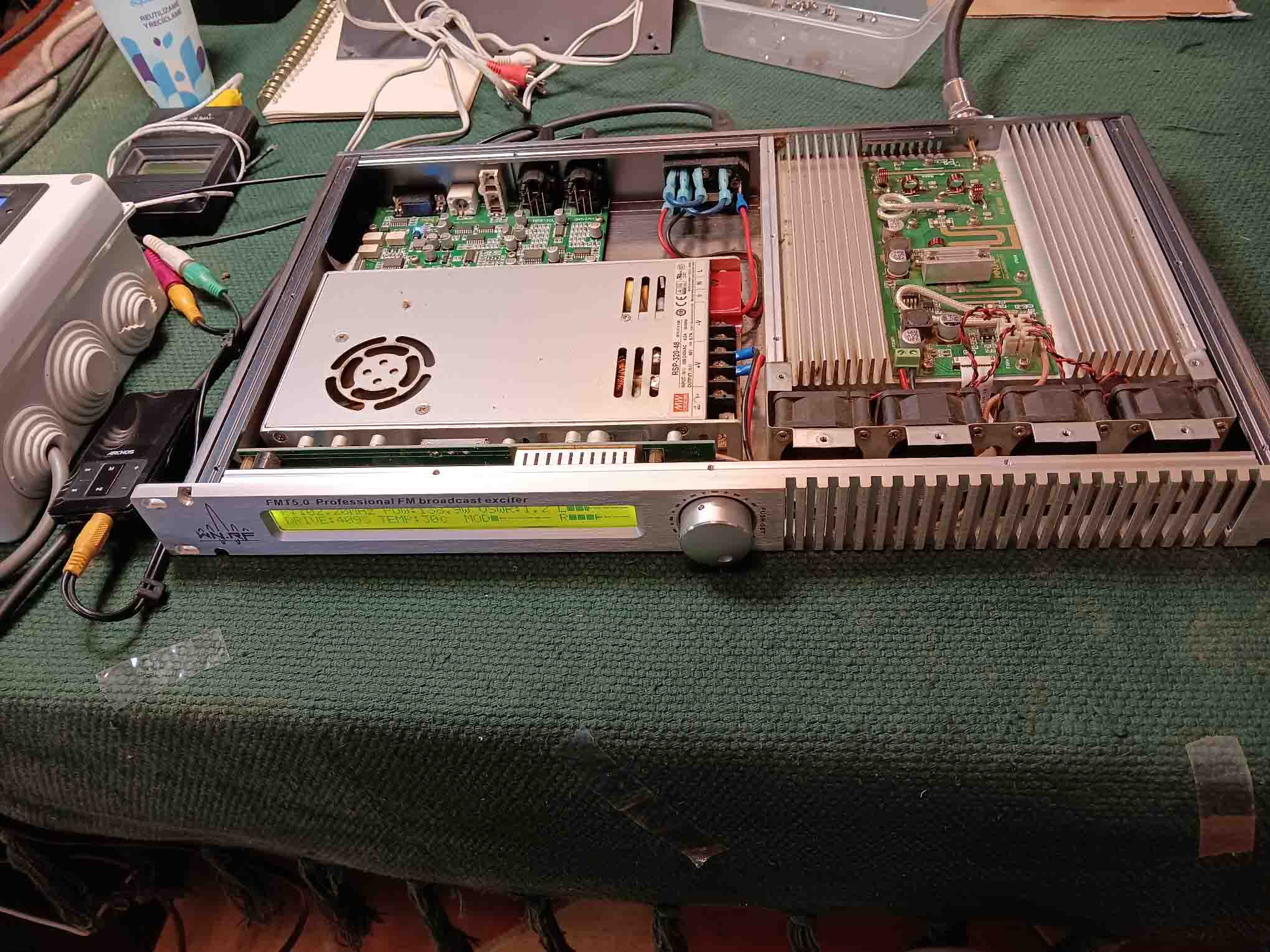
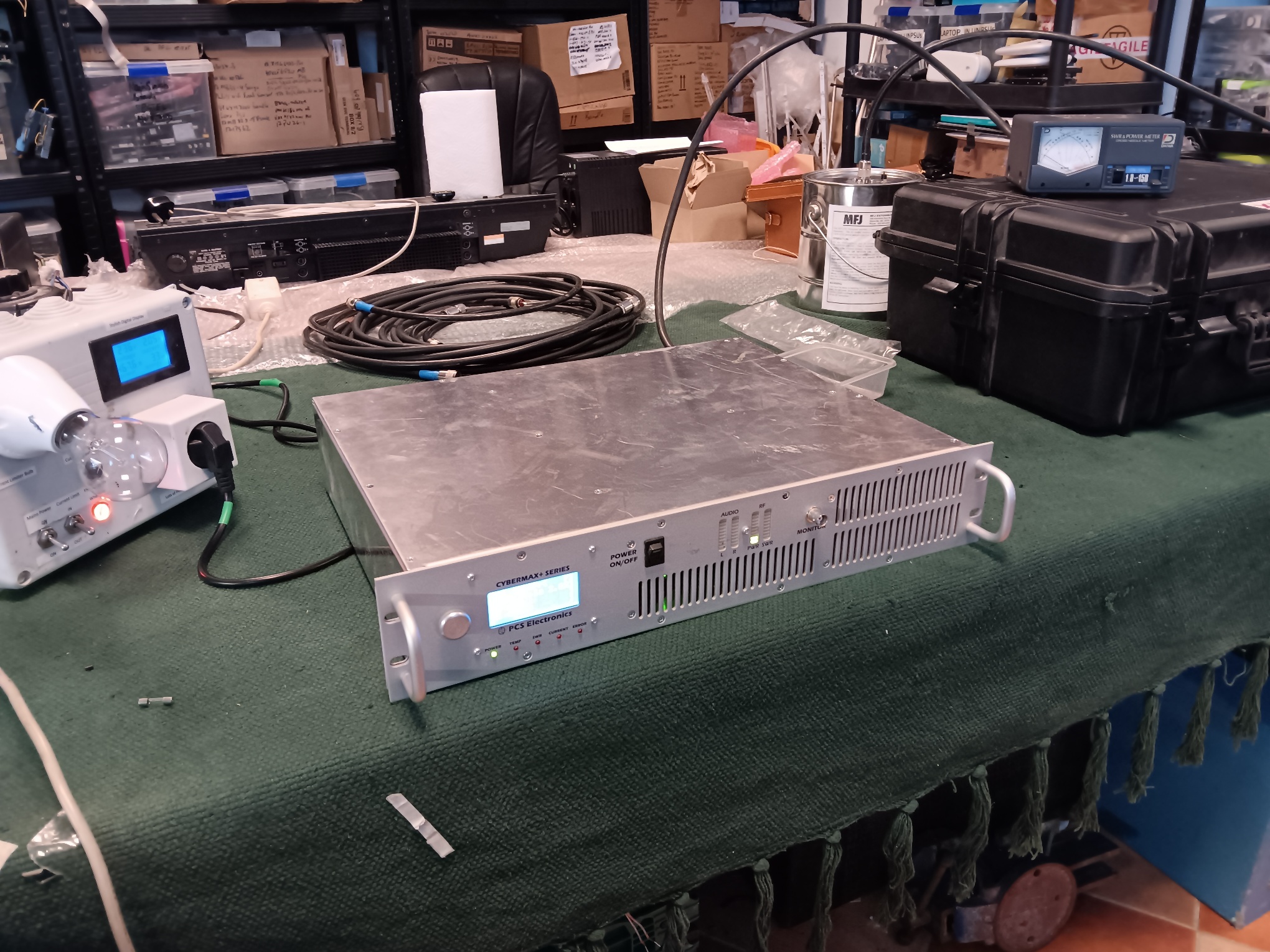
And for the many reasons stated about, least of all I have no plans to visit St. Peter just yet (Had a close call 3 years ago, not to be repeated) is why you don’t mess, even as a licences radio ham/technician, leave it to the experts like Seth who have dedicated most of their life’s to ‘Fault-finding’ and then repair. As usual I am eternally grateful, I’ll run some tests in a controlled Radio Station environment and see how we go.
A dear friend and I admire his skills as a radio operator. BUT, I an terrified when the lid is off his various PA amplifiers and he points and prods when the power is on. A great friend, but the kiss of life?????