

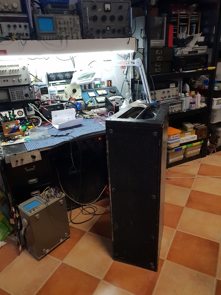
Meyer Sound M2D powered loudspeaker
A customer brought several of these large powered loudspeakers in for repair. They had all seen heavy combat in the field and as usual, I get the stuff that has been messed with by every man and his dog after they have given up.
Not seen these before, so I thought I would hunt around for some information and diagrams. Nothing came to hand easily. So, emailed the manufacturer in the USA, Meyer Sound, Berkley. Normally out of production equipment, the manufacturers are okay with providing data. But with this lot, I met a brick wall.
Just taking one of the loudspeakers, I will give you a quick rundown as to what was found and what had to be done. May be of interest should anyone reading this be confronted with one of the same.
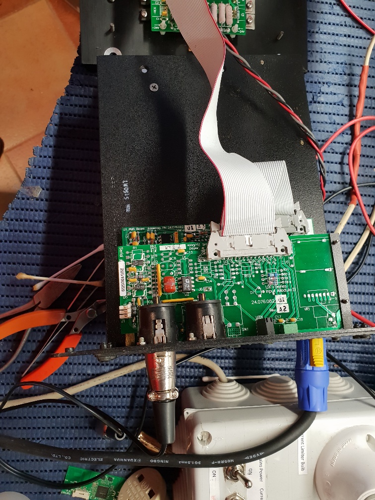
Firstly, they weigh approx 4 tons each so walking them around the workshop is fun. This particular one, when powered up, showed the power and limit LEDs flashing. The power supply and input boards are all in one removable unit. So that was taken out. The power amplifier section again is a module in itself. Again, that was removed. The two units are connected together with a power cable and a flat ribbon cable. The latter had been ripped out by the previous repair attempt, leaving the cable headers in the sockets. Great. Put those back together. Disconnected the power supply and tested that on it’s own. Under a resistive load, it worked fine. I was surprised to see that the power unit was a standard Meanwell 48V power supply. Now Meanwell make all kinds of power supplies and generally are good. The fault was obviously within the power amplifier section.
Without the luxury of schematics, there was much head scratching. Basically the amplifier is made up of two parts, one amplifier for the mid range and high frequencies, the other is for the bass. Both amplifiers have 4 complementary P and N channel MOSFETs each. Remember I said there was one voltage supply line? Looking at things, the output stage has a virtual 0V pegged halfway around the 48V rail. The pre amp stuff on the 3 piggyback boards have a similar arrangement, but derived from 7815s and 7915s regulators. A few of the MOSFETs were short circuit. One MOSFET sat on it’s own and this seemed to be responsible for the floating 0V line for the power stage. That was short circuit also. All the other small transistors were tested and were okay. There were 2 x dual OP amp chips and 2 x quad OP amp chips. The dual MOSFETs seemed to be driving the power MOSFETs and one of the quad MOSFETs seemed to be linked to audio and protection. With all the MOSFETs changed, it was powered up. Now the power supply was running so we had no shorts. But no audio. The muting relay operated and high and low frequency signals were getting to the board. Having this floating 0V line makes measuring DC conditions awkward. I noticed one of the dual OP amps was getting hot. Ah! I thought. Changed that and powered up again. This time there was a low output from the bass unit, only before the power supply went into protection again. The new MOSFET in the floating power section was dead. So, this time, not wanting to waste more money on killing transistors, I replaced all the OP amps. I used TLO82s and 84s. All resistors checked. Power up. Now we had output on both loudspeakers and all seemed happy. So, moral of the story, if something fails on this board, the DC conditions get messed up and cause havoc. Replace all 4 x OP amp packages to start with. I can see why the simple single rail power supply is used as it does make that side of things simple and reliable.
The Spanish dealer gave me a quote for a replacement board at over 1900€ Yeah right.


Thank you for the good information.