Sansui AU-X701
Here is another example of an amplifier that has been around the block many times hoping for a repair. As usual ending up at the stupid Guiri (Spanish slang for foreigner), i.e. myself.
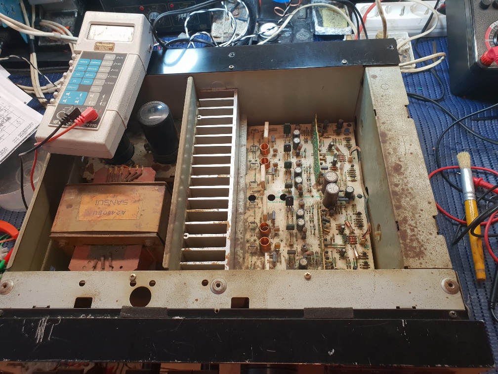
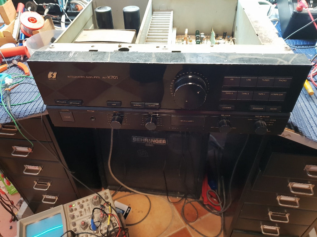
The AU-X701 Sansui is a very nice amplifier, dating around the mid to late ´80s. About 100 Watts a channel if I recall. This particular amplifier has certainly had a hard life. Lots of scratches and looking at the insides would appear to have suffered quite a few spillages, probably being used in a bar, under the counter.
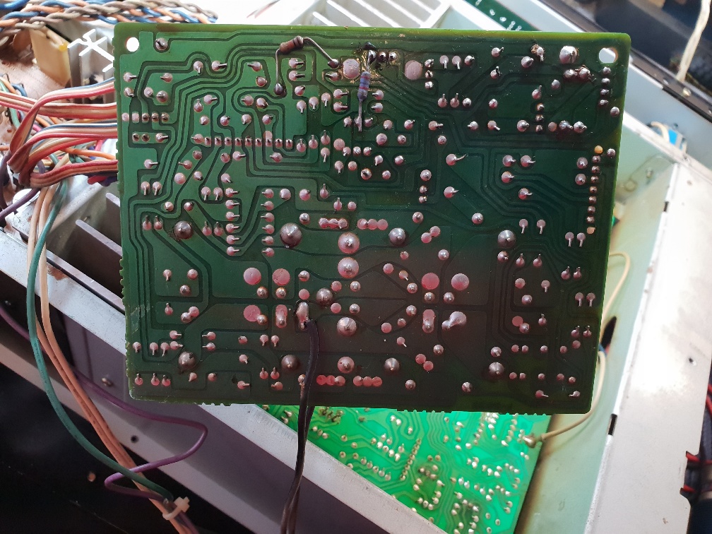
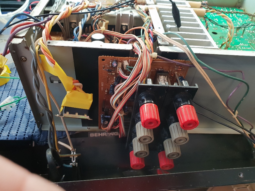
The report was, that when powered up, it would take approx 10 minutes to get to a point where the protection LED became stable and the output relays operated. The protection circuit is based around a TA7317P. It is complicated and the protection board checks a number of conditions, DC offset, over voltages, abnormal audio, whether you have had too much to drink etc. Both left and right channels have a board that looks at different parts of the circuit where it signals to the control board sat at the rear of the amp where the speaker relays and connections live. To get to this board, the rear of the amp has to be disassembled and the board hung outside the chassis keeping it clear from shorting out. The customer had said someone had replaced all the output transistors, but this had not helped. What a waste of money!
Normally, when the amp is first switched on, the power light flashes around twice a second, driven by a bistable circuit on the protection board. In this case, the LED was flashing with a rate that looked like 25 Hz. No odd voltages were present around the output stage and the transistors read okay. The only copy of the workshop manual was far removed from the original and part numbers almost blurred out. There are lots of electrolytics on this board and I recalled that there was a supply taken off a tapping from the mains transformer and half wave rectified. Lots of head scratching with the scope, there was a line which had a lot of ripple when cold. A hair dryer and can of freezer pin pointed a couple of electrolytic capacitors were open circuit. With these replaced along with a few other suspects, we now had a power LED that flashed at the correct speed and a few seconds following normal operation. Feeling quite happy, the rear of the set was assembled ready for a final test.
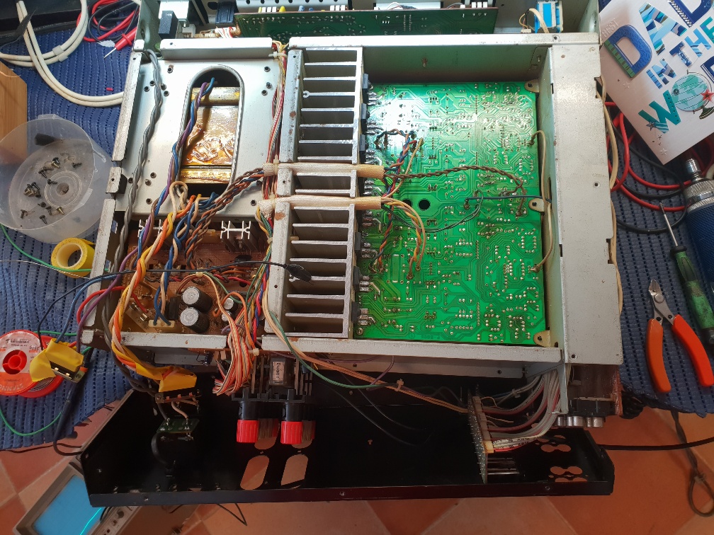
My happiness was dispatched when I found that the right hand channel was dead. The main board was in a filthy condition and loads of dry joints. Attending to that made no difference. I noticed that everything on the right hand channel was cold, although supply lines were present. It suggested nothing was being driven. DC conditions proved that most of the power devices were not conducting. At the front end of the amplifier section is a longtail pair configuration up using a double JFET package. All DC conditions showed that this was up at the supply rails voltage wise. Had a quick pray hoping this JFET jobby had not been damaged. Readings around the bias circuit again were odd. So, removed all the components in order that they could be tested cold. One transistor, Zener diode and 2 resistors later having been replaced, let’s try again. Deep joy, output correct and all was well. Set up the bias, test under load and off for a stiff drink.