

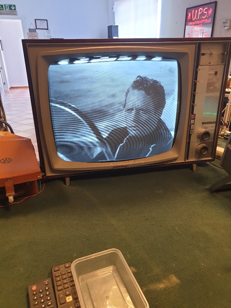
Philips 23TE534A
To end the day, after working on boring flat screen TVs and other things for clients that don’t appreciate the work put in, I thought I would revisit a TV I bought years ago. I had initially done some basic work to get it to produce a picture of sorts, then it failed all together. So, here we go.
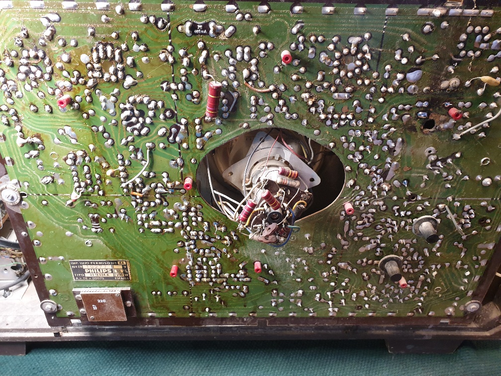
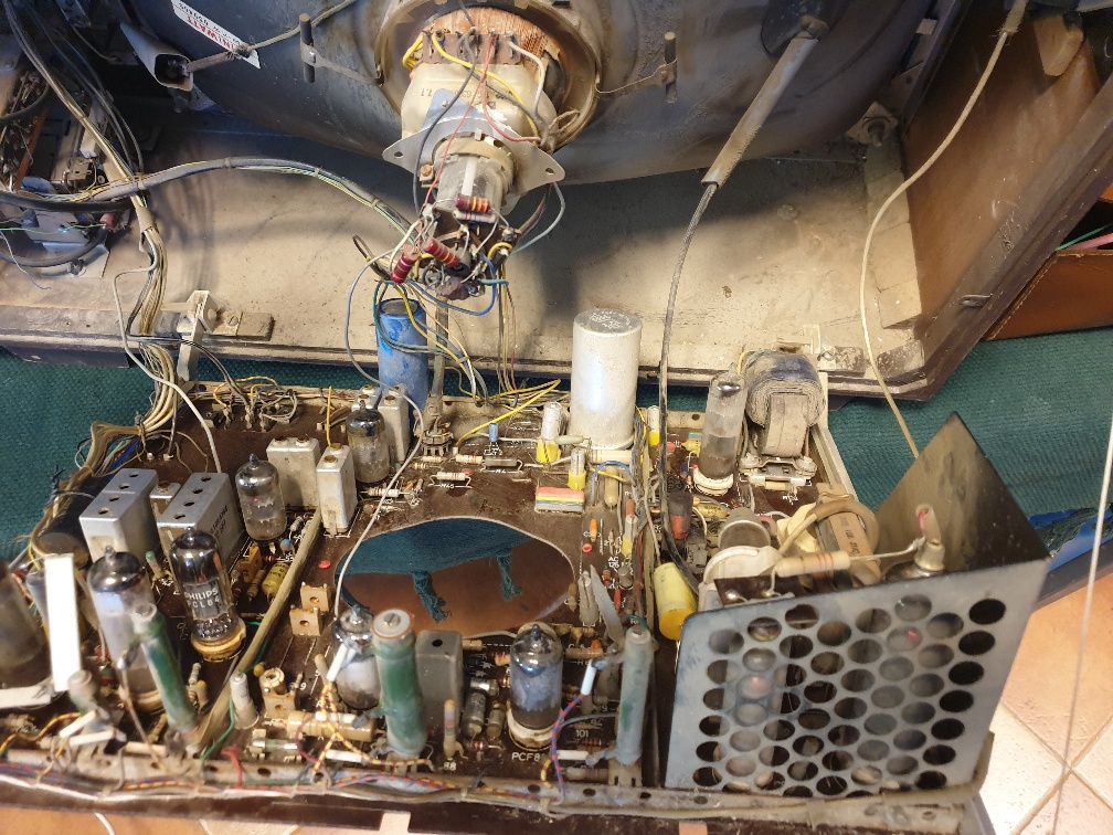
The set dates back to around 1967. Would have been quite a luxury here in Andalucía. 625 line set only, with VHF and UHF tuner. Also can work on 220v and 120v (looks like some sort of voltage doubler for the HT when on 120V). First off was to rework the numerous dry joints and broken tracks on the PCB. Luckily, the various high wattage resistors are bolted on stand-offs and wired to the board, so minimizing local burn ups. There were a number of capacitors faulty, boost reservoir, mains filter and others around the timebase and LOPT sections. The boost res cap had burnt its way through the board so had to been cleaned up. I had checked the CRT before starting out and the BK said it looked okay. So, slow power up with the current limiter. Very annoying now, at the age of 64, I can only just hear the line whistle, if I tape my right ear to the LOPT.
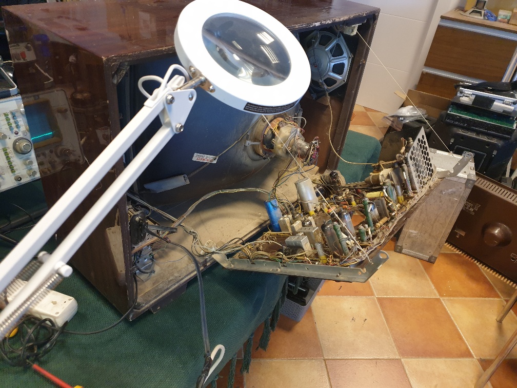
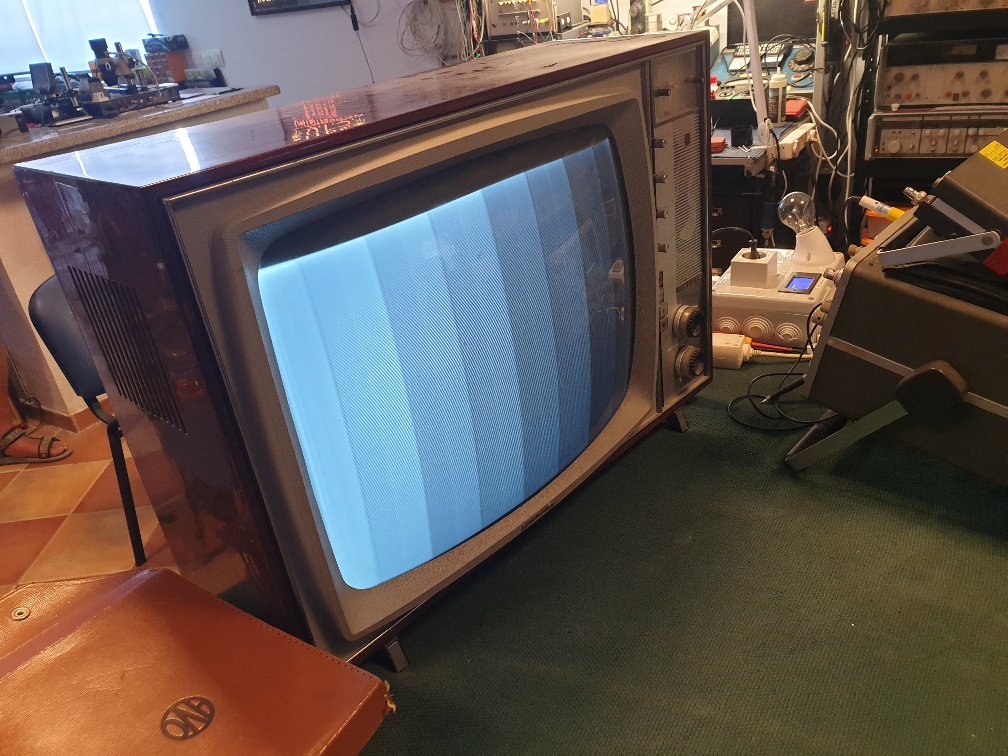
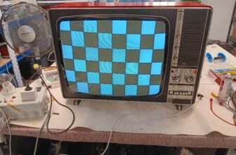
After about 5 mins, gave her full power, keeping an eye on the current and pending signs of exploding things. Eventually got a cramped dim raster. Applied a RF signal from the generator. After resoldering the area round the audio output stage, I managed to get the test tone. But no test bars up and very little in the way of vertical and horizontal sync. The problem is, that I could not find a schematic anywhere for this set, so fault finding is very awkward. Attention turned to the video IF stages. This uses PCF200 and PCF201 valves. And, in my rack of 3,500 valves I do not have these types. I did buy some new ones years ago for a similar set, so robbed that set for a test. No joy. Hoping I did not have an IF transformer fault. Went about checking all the components one by one, trying to keep the PCB tracking in place. A few components out of spec but nothing I would have thought to give no video. The fact I had no sync, indicated the fault was within the IF stages. I could not find any signals worth speaking of with a scope. But, the PCF201 was running quite cold. After messing about, I eventually found a small choke open circuit. Resoldering violently seemed to cure it. Now we had a locked picture but no contrast. The anode load resistor in the video output stage, a PCL84, was almost open. That replaced and a new PCL84 rewarded us with a good picture, albeit a bit low in height. A replacement PCL85 sorted that out.
The sound was still very intermittent due to dry joints around the audio valves. Load more cleaning up and 2 reels of solder later. Now, without a circuit, I was a bit puzzled by the valve set up. There is a PCL 86 and a PL 84. And, I could not find an audio output transformer anywhere. Shall I assume that this set has one of those silly Philips high impedance loudspeakers, doing away with a transformer?
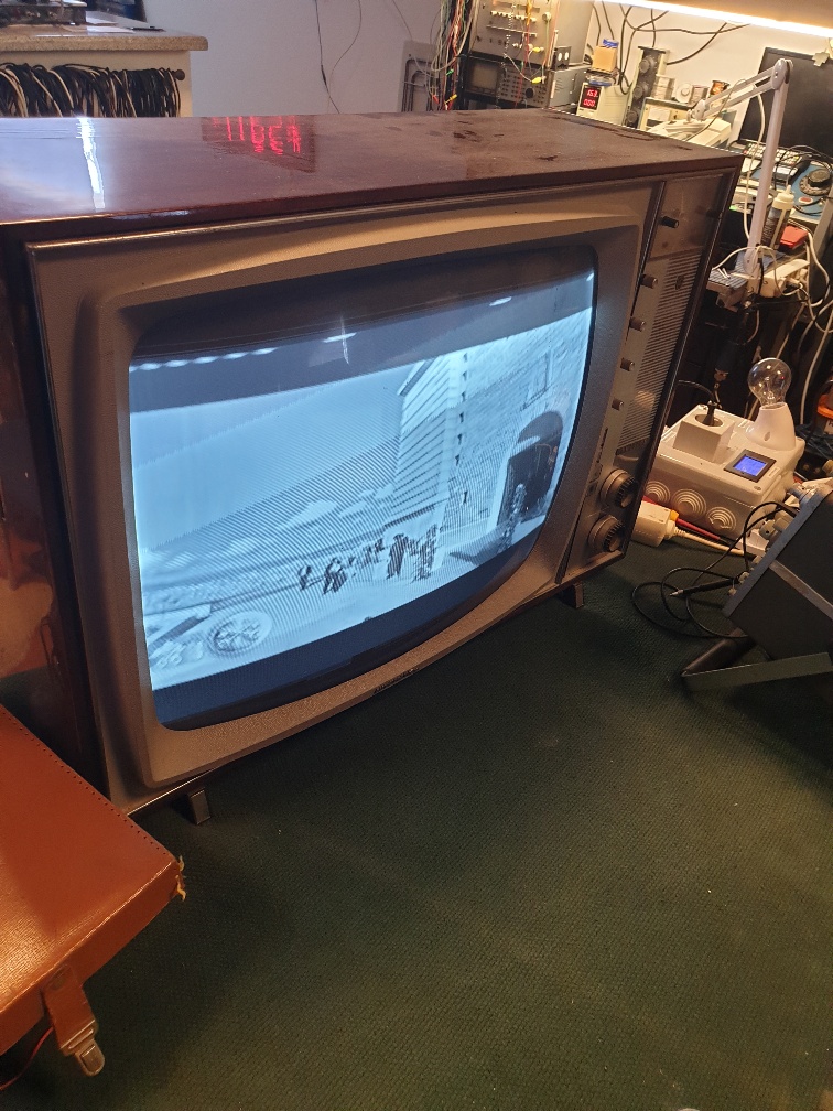
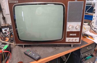
Nice TV. Has a working clock – timer and a tone control! The audio is very good. So, what better way to end a week by watching an episode of The Prisoner”?
Philips 23TE534A
Para terminar el día, después de trabajar en aburridos televisores de pantalla plana y otras cosas para clientes que no aprecian el trabajo realizado, pensé en volver a visitar un televisor que compré hace años. Inicialmente hice un trabajo básico para que produjera una especie de imagen, pero luego falló por completo. Así que, aquí vamos.
El conjunto data aproximadamente del año 1967. Habría sido todo un lujo aquí en Andalucía. Solo equipo de 625 líneas, con sintonizador VHF y UHF. También puede funcionar con 220 V y 120 V (parece una especie de duplicador de voltaje para el HT cuando está en 120 V). Lo primero fue reelaborar las numerosas uniones secas y pistas rotas en la PCB. Afortunadamente, las distintas resistencias de alto voltaje están atornilladas a separadores y conectadas a la placa, lo que minimiza las quemaduras locales. Hubo varios condensadores defectuosos, depósito de refuerzo, filtro de red y otros en las secciones de base de tiempo y LOPT. El límite de resolución de impulso se había quemado a través del tablero, por lo que hubo que limpiarlo. Revisé el CRT antes de comenzar y el BK dijo que se veía bien. Entonces, encienda lentamente con el limitador de corriente. Muy molesto ahora, a la edad de 64 años, solo puedo escuchar el silbido de la línea si pego mi oreja derecha al LOPT.
Después de unos 5 minutos, le dio todo el poder, manteniendo un ojo en las señales actuales y pendientes de explosiones. Finalmente obtuve una trama tenue y estrecha. Se aplicó una señal de RF desde el generador. Después de volver a soldar el área alrededor de la etapa de salida de audio, logré obtener el tono de prueba. Pero no hay barras de prueba arriba y muy poca sincronización vertical y horizontal. El problema es que no pude encontrar un esquema para este conjunto en ninguna parte, por lo que encontrar fallas es muy complicado. La atención se centró en el vídeo de las etapas IF. Esto utiliza válvulas PCF200 y PCF201. Y en mi rack de 3.500 válvulas no tengo estos tipos. Compré algunos nuevos hace años para un TV similar, así que lo robé para probarlo. Sin alegría. Esperando no haber tenido una falla en el transformador IF. Verifiqué todos los componentes uno por uno, tratando de mantener el seguimiento de la PCB en su lugar. Algunos componentes fuera de especificaciones, pero nada que se me hubiera ocurrido dar sin vídeo. El hecho de que no tuviera sincronización indicó que la falla estaba dentro de las etapas IF. No pude encontrar ninguna señal de la que valga la pena hablar con un visor. Pero el PCF201 estaba funcionando bastante frío. Después de probar, finalmente encontré un pequeño circuito abierto del estrangulador. Resoldar violentamente pareció curarlo. Ahora teníamos una imagen bloqueada pero sin contraste. La resistencia de carga del ánodo en la etapa de salida de video, una PCL84, estaba casi abierta. Esto lo reemplazó y un nuevo PCL84 nos recompensó con una buena imagen, aunque un poco baja en altura. Un PCL85 de repuesto solucionó ese problema.
El sonido seguía siendo muy intermitente debido a las juntas secas alrededor de las válvulas de audio. Cargue más limpieza y 2 carretes de soldadura más tarde. Ahora, sin circuito, estaba un poco desconcertado por la configuración de la válvula. Hay un PCL 86 y un PL 84. Y no pude encontrar un transformador de salida de audio por ningún lado. ¿Debo suponer que este equipo tiene uno de esos tontos altavoces de alta impedancia de Philips que eliminan el transformador?
Bonita televisión. Tiene un reloj que funciona: ¡temporizador y control de tono! El audio es muy bueno. Entonces, ¿qué mejor manera de terminar una semana viendo un episodio de The Prisoner”?


Crt tv philips