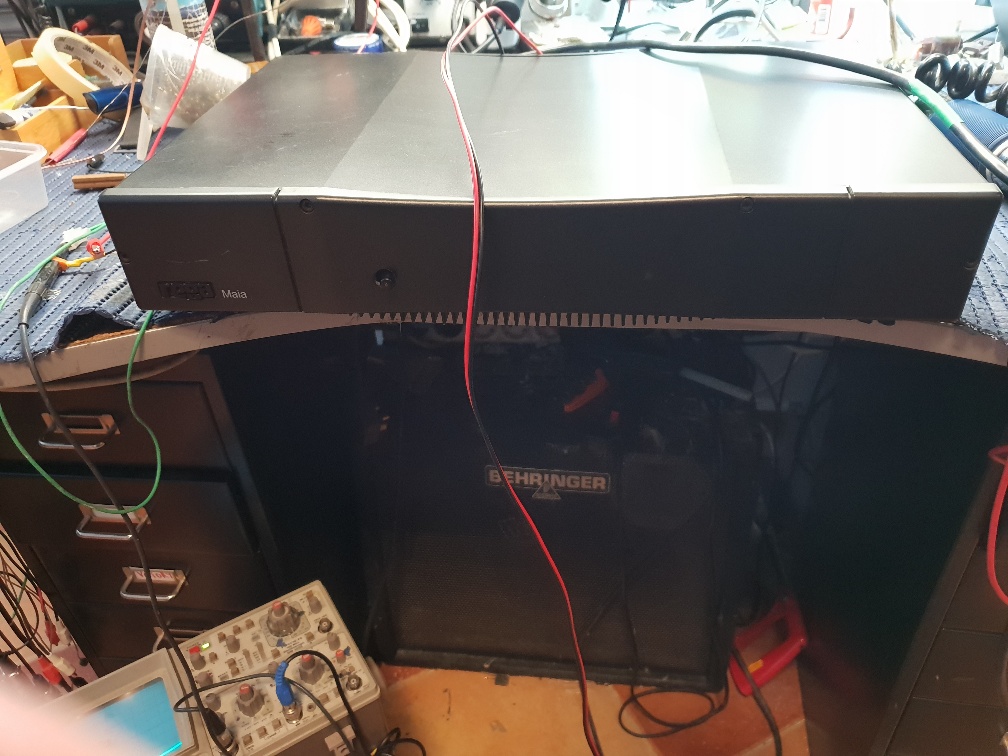
A gentleman from Dutchland bought in a couple of Rega Maia amplifiers today. Always a bit suspicious when someone brings in two similar bits of kit, both faulty. One was a Maia integrated amp, the other was a Maia power amp. Some paperwork in the boxes suggested that previous repairs had been carried out in Dutchland, confirming my worries.
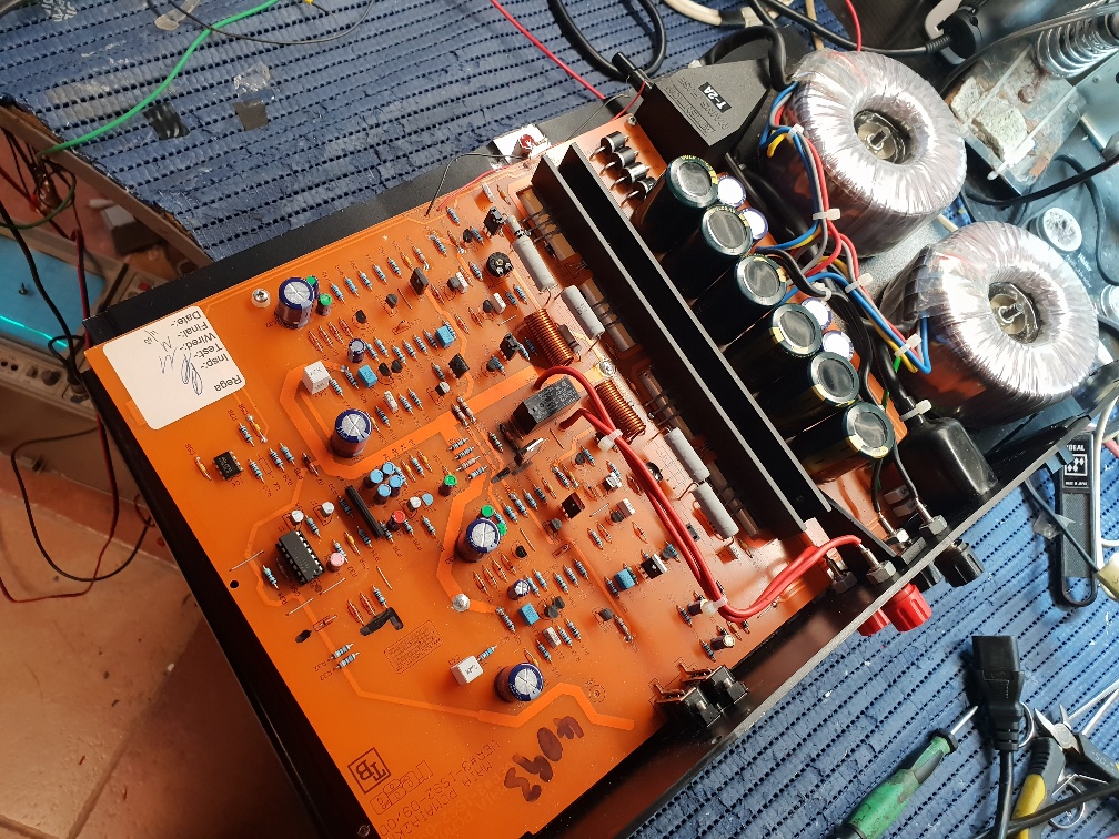
Power amp.. The report was that when it was powered up, you no longer heard the protection relay click, but the power light was on. So, powered it up using the current limiter, along with an audio input, having checked for short circuits around the power transistors before. Sure enough, power light on and the scope showed a good output on the transistors. So attention turned to the protection circuit. Not being able to get a diagram, started looking for the obvious. In the middle of the main board sat what looked liked to be a fat Zener diode. It had obviously got very hot, burnt the board a bit and was dry jointed. The Zener tested okay, so resoldered and try again. Still nothing. So no volts being dropped across the zener, meaning there was an open circuit somewhere. As it happens, one of the tracks was damaged, so had to be bridged. Now with the power on, the power light came on for a second, then went out and the Zener got very hot. Also noticed that a CMOS chip, CD4093 was baking hot. This seemed to be in the power start up – protection circuit. Looking around and saw there was a series regulator, LM7812 being fed by the Zener. The 7812 was short circuit, sending 24 Volts where 12 should have been. With that replaced and the CD4093 removed, DIL socket in place I refitted the CMOS chip just for a laugh. To my amazement, all worked! Well done CMOS chip for radiating 3 Kilowatts.
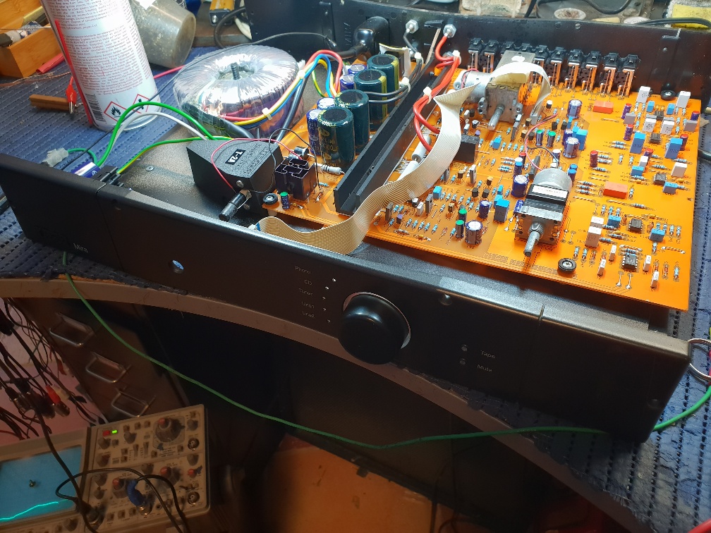
Integrated amp. Bit of a silly thing this. One control knob. This is a rotary encoder. Turn it and it changed the volume. Push and turn and it selects one of the 6 or so inputs. So joy of joys when powering it up, the Input LED indicated just flashed up and down and couldn’t be made stable. With the amp in bits, I started to blame the encoder control, but the scope showed it’s outputs were all good. It did change the volume so the fault was not there. Now this is a stupid design. On the main board, you have a multiway switch bank with a shaft coming out where a knob should be. It is driven by a motor when a processor controls depending on the input selected. So, somehow the processor needs to know where the switch is so it can set it’s required position. In the switchbank, there must be an encoder as well. This must have been dirty, sending incorrect data to the on board confuser. With that cleaned, all was good. Same thing done for the volume control which again was a motor driven potentiometer assembly with a shaft sticking out waiting for a knob to be placed on it. Why not have two simple controls? Why make things complex when a simple switch could be used that has been done for centuries? Anyway, all working, but a brain tester for certain.