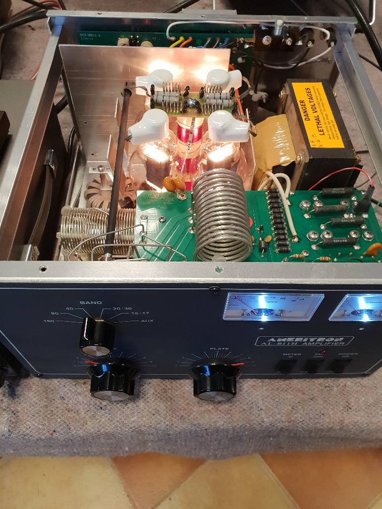
Ameritron AL-811H linear HF amplifier
This amplifier came into the shop for repair. Nicely made basic amplifier, but always worth knowing the history of previous faults and may be worth noting some of the points below to save time.
The first time we heard of this amplifier, it was suffering with output valve faults. It was fitted with PSVANE valves, which in my opinion, are not the best on God’s planet. 2 of the 4 were faulty, one with open circuit heaters and the other with a hole in the wafer-thin glass.
A new set of RCA 811s were obtained from my favorite supplier in the UK, Langrex, formerly RST. I have been using the company since the 60s. The owner of the amplifier replaced the valves but notices things soon run hot. Once the amplifier was in the work shop, we had to dig deeper.
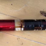
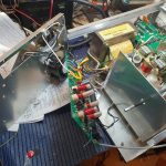
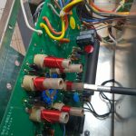
A quick look showed that the anode load coil was burnt out and the new RCA valves looked as if they had been having a struggle. A new choke coil was fitted and one valve fitted, anode cap off, to see what was going to happen. Powered up with a Variac and current limiter. HT was ok at around 1,700 volts. Connecting the anode to the valve, saw a rise in current, with the valve starting to glow cherry red on the anode. This was probably the cause of the anode choke failing due to excessive anode, plate current. Neither meter on the front panel gave any indication of current being drawn. Following the bias arrangement on the diagram, lead to looking for a short circuit. D16 and on other diode on the meter-HT board were found to be short. With these replaced, we now had a valve that was not drawing current, but we had a meter showing negative grid current. Normally this is due to a grid to heater short, but all the valves tested okay. There was however only a few Ohms between the heater supply and chassis ground. There is a MOV device which connects the heart supply to chassis to prevent damage should a valve flash-over occur. Once the rear of the amplifier had been removed and the main board lifted away, the MOV device was shorted. This was replaced. This is the red components seen hiding under the 2 electrolytic capacitors in the picture below. You also need to check the small value capacitors around the heater decoupling arrangements. With everything reassembled and all the valves fitted, we now had normal operation, with 75mA anode plate current with the amplifier keyed but no RF drive. Connected up to a transceiver for test gave good results. Now packed off to be tested with a dedicated antenna array.




Fantastic fault finding and repair as always
Hi, i looking some info aboyt RF choke , because i need to rewind myslef, but i can find what is org diaeter of wire and how mny turn need to be soin. Can You help ? Thanks, 73