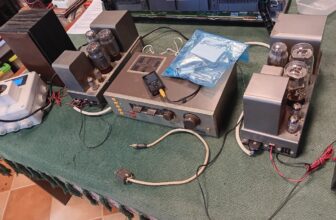
I have had a couple of D115s recently.
These are lovely amplifiers, but not designed to be serviced. Nine 6550s / KT88s and loads of drivers, phase splitters, long tailed pairs, ICs, transistors massive mains transformer, healthy output transformers etc go to make a unit which needs a block and tackle to get it onto the bench. Oh, I forgot to mention, you will need an agreement with the national grid prior to switch on. They eat up about 340 watts just sitting there, that’s before you take the handbrake off. The inrush current exceeds 8 amps at switch on and that’s softened by a slow start circuit.
The amps are well made in typical U.S. fashion. They use a large one piece through hole plated PCB. This seems to be a bit of a down. With several years of warming up and cooling down, dry joints and failure occur. This can cause intermittent faults, strange DC conditions around the driver and output stages. These stages have numerous variable settings to ensure that the correct balance conditions can be achieved. This is all fine and dandy, but the more components and larger PCB areas there are, the more obscure faults arise.
Typical faults so far
I have seen the cathode resistors in the output stage change value and go open circuit. If this happens in one associated 6550, you probably will not notice any change as far as the audio is concerned. Its’ other three friends tend to cover up for it. A discerning ear may tell you something is wrong if the amplifier is being driven hard. The first pointer is the associated 6550 runs cool and you cannot set up the standing current as per the instructions.
Setting up the quiescent current is straight forward, but requires you to grow an extra hand. Measurement is done by using a DVM to read a voltage drop across a 0.1 ohm resistor is the cathode circuit, conveniently converting milliamps into millivolts. So, 1) carefully hold the meter probes onto the small test points, making sure you don’t slip and blow the whole lot to the promised land, 2) holding the mini adjusting tool in your mouth and keeping an eye on the DVM, adjust for .065 volts (65 milliamps (if I recall).
NOTE – You are now leaning over a very hot amp which has been on for an hour or so with 8 X 6550s throwing 25+ watts a piece at you (plus the 6550 in the power section acting as a stabilizer, and all the other valves), It’s a hot sunny day around 30 degrees and beads of perspiration are about to drop onto the main PCB. This is not good as we are looking at a HT of some 450+ Vdc. Suggest you reach for the knotted hankie or tea towel. Another point to keep in mind is the plastic caps on the main filter – smoothing electrolytic capacitors have a habit of cracking with age. You certainly want to keep away from the screw terminals on the top, as this baby will turn you into a grease stain before you can say, ouch that hurt.
Another annoying fault was intermittent blowing of the mains fuse. In the UK version the fuse is rated at 3.15 amps.
On the bench, the amp was connected to a Variac, Isolation transformer and in series with an adjustable trip. After the in-rush current dies down and the amp has warmed up, the standing current was about 1.5 amps with about 15 watts a channel. The current was stable and I did not see any blue flashes from any of the 6550s as expected (hoped for). Then after about 5 minutes, the mains current increased to 2 amps and back down again. This happened a few times and tripped at 3 amps. Now, what was happening? Removing the output valves in channel one and two in turn did not see the fault cleared, indicating there was a power supply or common fault. Very time consuming. A pre test of all 9 KT88s / 6550s on the AVO tester showed nothing obvious.
Tucked away on an edge / corner of the PCB, where you cannot get at (chassis has a large return), sits a little -40 volt DC power supply. This feeds the potential divider network for the output stage. Monitoring this stage showed that after a few minutes of operation, -40 VDC dropped to -30 VDC and back up. This was the fault. With a reduced grid bias, the output stage started to draw high current and there we have it. If you are careful, you can resolder some of the components around the area. To take the PCB out, would not be a viable option, unless the owner has deep pockets.
Another problem that I have had is within the PSU section, there is a string of various Zener diodes in a protection circuit. These are designed to prevent damage due to excessive voltage during certain fault conditions. For whatever reason, I have seen individual diode fail, causing odd faults.
So, nice amplifiers with plenty of output and overhead, but boy they packed with loads of stuff to make your head hurt.